
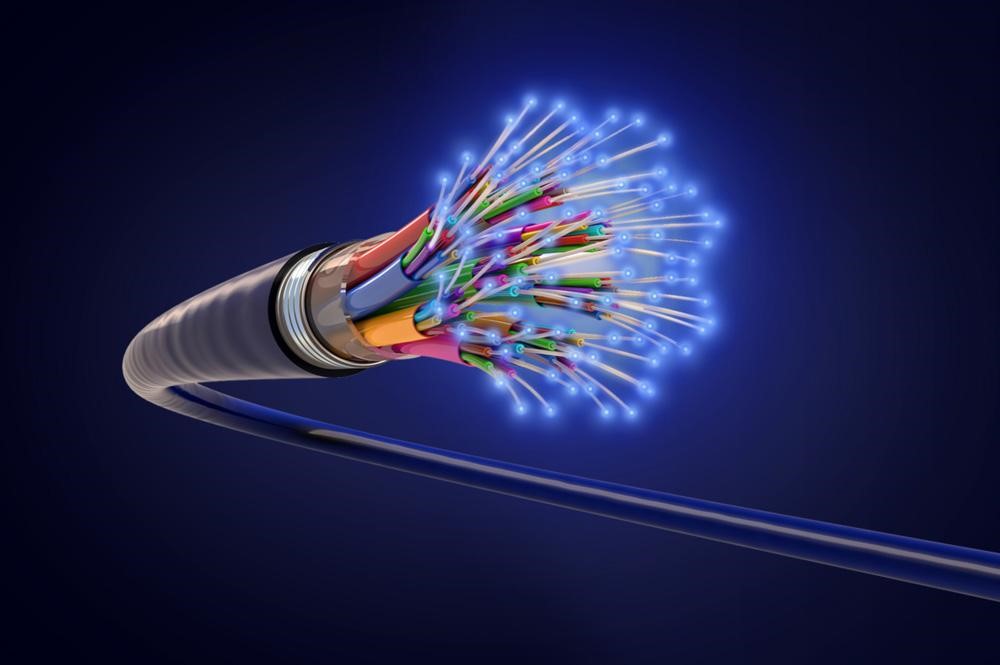
In the world of telecommunications and data transmission, maintaining optimal network performance and reliability is crucial. One of the key factors that can impact network integrity is the loss of signal in optical fiber. Signal loss, also known as attenuation loss or fiber optic attenuation, measures the amount of light loss between the input and output of a fiber optic cable. This article will delve into the top losses in optical fiber and guide you on how to calculate and evaluate fiber link performance.
Related Link: Bus Duct: Electrical Power Distribution and a Busway
Types of Losses in Optical Fiber
Losses in optical fiber can be classified into two categories: intrinsic optical fiber losses and extrinsic optical fiber losses. Intrinsic losses are caused by the inherent characteristics of the fiber itself, while extrinsic losses are influenced by operating conditions and external factors.
● Intrinsic Optical Fiber Losses: These losses include absorption loss, dispersion loss, and scattering loss. Absorption loss occurs due to the absorption of light energy by the fiber material itself. Dispersion loss is caused by the spreading of light pulses as they propagate through the fiber, leading to signal distortion. Scattering loss is the result of light scattering caused by structural defects within the fiber.
● Extrinsic Optical Fiber Losses: Extrinsic losses include splicing loss, connector loss, and bending loss. Splicing loss refers to the loss of signal when two fiber optic cables are joined together. Connector loss occurs when light is lost at the connection points between cables and optical devices. Bending loss occurs when the fiber optic cable is bent beyond its specified bend radius, resulting in signal attenuation.
Wanting to stay up to date with workplace technology? Visit our blog today!
Standards for Fiber Loss

The Telecommunications Industry Association (TIA)/Electronic Industries Alliance (EIA) develops standards that specify the transmission requirements and performance for fiber optic connectors, cables, and other components. These standards are widely accepted and used in the optical fiber industry. The maximum attenuation, expressed in dB/km units, is an essential parameter for measuring fiber loss.
Related Link: What is a Colocation Data Center? Colocation Facilities Guide
Calculating Losses in Optical Fiber

To evaluate the performance of a fiber link, it is necessary to calculate the losses involved. The following calculation can help determine the maximum signal loss across a given fiber link during optical cable installation:
Total Link Loss = Splice Loss+ Connector Loss + Cable Attenuation
Cable Attenuation (dB) = Length (km) x Maximum Cable Attenuation Coefficient (dB/km)
Connector Loss (dB) = # of Connector Pairs x Allowance of Connector Loss (dB)
Splice Loss (dB) = # of Splices x Allowance of Splice Loss (dB)
By applying these formulas, the total loss can be estimated by considering the worst-case variables within a fiber segment. However, it is important to note that the calculated total loss serves as an estimation, as the actual loss may vary depending on different factors.
Let’s think about how this works in practice. Let’s pretend a 10 km gap exists between two buildings, and a single-mode fiber optic cable operating at an optical wavelength of 1310 nm has been installed. There are two sets of ST connectors and a splice in this cable. How the costs would be estimated is as follows:
● Calculate the fiber cable attenuation loss. Based on the standard chart, the light attenuation for a 1310nm single-mode fiber optic cable is 0.5dB/km. Therefore, the total cable attenuation would be 0.5dB/km × 10km = 5dB.
● Calculate the total connector loss. Use the EIA/TIA maximum loss/pair (e.g., 0.75dB) and multiply it by the number of connector pairs (2). In this case, the total connector loss would be 0.75dB × 2 = 1.5dB. It’s important to consult the fiber optic cable specifications provided by suppliers for the actual connector loss values.
● Calculate the total splice loss. Use the TIA/EIA maximum loss per splice (e.g., 0.3dB) and multiply it by the number of splices (1). The total splice loss would be 0.3dB × 1 = 0.3dB.
● Account for any other component losses, such as attenuators, if applicable.
● Add the cable loss, connector loss, and splice loss to obtain the total link loss. In this example, the total loss would be 5dB + 1.5dB + 0.3dB = 6.8dB.
● While these calculations provide estimates, the most accurate approach is to use an Optical Time-Domain Reflectometer (OTDR) trace for an actual link.
Power Budget and Power Margin
The link loss value is essential when considering the power budget and power margin. The power budget is calculated by determining the difference between the transmitter output power (PT) and the receiver sensitivity (PR). The power budget (PB) formula is PB = PT – PR. For example, if the average output power of the transmitter is -15dBm and sensitivity of the receiver is -28dBm, the power budget would be -15dBm – (-28dBm) = 13dB.
The power margin, also known as the safety margin, represents the available power after subtracting the link loss from the power budget. The power margin (PM) formula is PM = PB – LL, where PM is the power margin and LL is the link loss. Using the 10km single-mode fiber example, if the power budget is 13dB and the link loss is 6.8dB, the power margin would be 13dB – 6.8dB = 6.2dB. A positive value for the power margin indicates that the link has sufficient power for transmission.
Looking for help with implementing workplace technology for your business? Contact us today.
Understanding Losses in Optical Fiber
Understanding the top losses in optical fiber and accurately calculating fiber loss are critical for ensuring optimal network performance and reliability. By considering both intrinsic and extrinsic losses and adhering to industry standards, data center owners can effectively evaluate the performance of their fiber links. The calculations of cable attenuation, connector loss, splice loss, and other component losses provide valuable insights into the overall link performance. By closely monitoring fiber losses and power budgets, data center owners can maintain a high-quality, efficient, and reliable optical fiber network.
Related Link: What is a Hyperscale Data Center? Full Hyperscale Breakdown
Last Updated on August 21, 2023 by Josh Mahan