The Important of Selecting the Right POE Cabling System
In the ever-evolving landscape of Information and Communications Technology (ICT), Power over Ethernet (PoE) cabling systems has emerged as a revolutionary solution, streamlining the deployment and management of network devices while optimizing power delivery. From smart buildings and IoT devices to data centers and enterprise networks, PoE technology has become the backbone of modern connectivity. However, with the plethora of PoE cabling options available in the market, choosing the most suitable solution can be a daunting task. This blog article aims to provide valuable insights, empowering you to navigate the decision-making process with confidence.
In this comprehensive guide, we will explore the fundamental aspects of PoE cabling systems, including different PoE standards, cable categories, and power delivery considerations. We will delve into the benefits and limitations of each option, as well as the factors that influence performance and efficiency.
A Step-by-Step Guide to Selecting the Perfect POE Cabling System
Power over Ethernet (PoE) cabling systems have become a critical component, enabling the seamless integration of power and data transmission in modern networks. Choosing the right PoE cabling system is crucial to ensure optimal performance, efficiency, and reliability. Consider these essential steps to make an informed selection, allowing you to harness the full potential of PoE technology for your network.

Step 1: Select PSE/PoE Type
The first step in choosing the right PoE cabling system is to determine the Power Sourcing Equipment (PSE) or PoE type that aligns with your network’s power requirements. PoE standards, such as IEEE 802.3af (Type 1), IEEE 802.3at (Type 2), and IEEE 802.3bt (Type 3 and Type 4), vary in power delivery capacities, ranging from 15.4W to up to 100W.
Step 2: Identify Permanent Link Distance
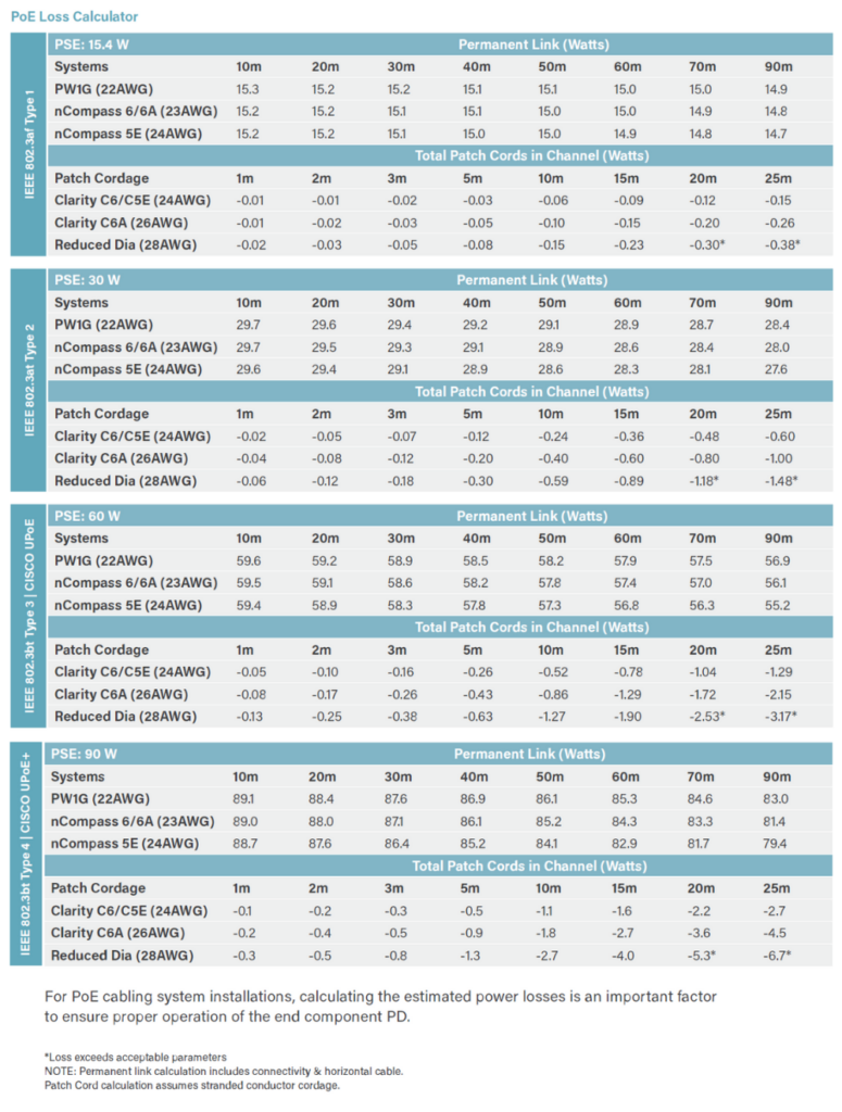
Next, locate your permanent link solution and document the value provided for the distance of the permanent link. The permanent link is the structured cabling between the PSE and the Powered Device (PD), and its length is a critical factor in determining the available power delivery.
Step 3: Select Patch Cord Type and Length
Finally, select the type and total length of the patch cords in the channel. Subtract this number from the value identified in the permanent link to calculate the maximum power delivered to the Powered Device.
EXAMPLE:
Let’s consider an example to better understand the steps and chart referenced above. Suppose you are using a 15.4W PSE and installing a Legrand nCompass PW1G cabling system with the following channel components:
- 70m permanent link
- 10m Category 6A (C6A) patch cords
To calculate the power delivered to the Powered Device, follow these steps:
- Permanent Link Distance: 70m (15.0)
- Patch Cord Length: 10m (-0.10)
Subtract the patch cord length from the permanent link distance: 15.0 – 0.10 = 14.9W
The PoE cabling system should provide the Powered Device (PD) with an estimated 14.9W (15.0W – 0.10W) of power at 20°C room temperature.
By following these steps, you can confidently select the appropriate PoE cabling system that meets your network’s power requirements, ensuring seamless power delivery and robust data transmission. Making the right choice in selecting a PoE cabling system will empower your ICT infrastructure with enhanced performance, future scalability, and reliable connectivity, propelling your network to new heights of efficiency and productivity.
Key Considerations for Optimal PoE Cabling Design Architecture
When designing a PoE cabling system, it’s essential to consider various factors to ensure efficiency, reliability, and safety. Here are some crucial considerations that can significantly impact the performance of your PoE cabling design architecture.
- Cabling Pair-to-Pair Current Unbalance:
One critical aspect to address in PoE cabling design is the pair-to-pair current unbalance. Unlike unbalance within a pair, which deals with the difference in signal transmission, pair-to-pair current unbalance refers to the distribution of power among the different cable pairs. Ensuring a balanced current distribution is essential for providing proper and functional power to end devices. To achieve this, refer to the manufacturer’s cabling system specifications for guidance and best practices.
- Cable Bundling Heating Effect:
Cable bundling can lead to increased heat buildup, affecting the performance and longevity of the cabling system. To mitigate this, adhere to the recommendations and guidelines outlined in Technical Service Bulletin TSB 184 and TSB 184-A. These guidelines prescribe bundling rise limits, typically less than 15°C, and cabling lengths to prevent excessive heating. If cabling temperature remains an issue, consider using a larger cabling gauge size (AWG) to reduce overall loop resistance and, consequently, minimize temperature concerns.
- Cabling Natural Power Losses:
Understanding the cabling’s natural power losses due to its design components is crucial. Refer to the manufacturer’s chart (A) to estimate the power losses from the Power Source Equipment (PSE) delivery to the Power Device (PD). It is essential to be aware that high ambient environments can add to these power losses, impacting the overall performance of the PoE cabling system.
- Elevated Ambient Temperatures:
Elevated and extreme ambient temperatures can further contribute to power losses in the cabling channel system. As a rule of thumb, be prepared for an additional 1-2 watts of extra power loss in such environments. Proper cooling and environmental monitoring are vital to maintain optimal PoE operation and prevent performance degradation.
Breaking down the 4 tiers of POE Standards
- 802.3af (802.3at Type 1) – PoE: 802.3af, also known as PoE or Type 1 PoE, is the initial PoE standard introduced by the IEEE. It provides up to 15.4 watts of power per port and is capable of transmitting power and data over two twisted-pair cables in an Ethernet cable. This standard is suitable for low-power devices like IP phones, wireless access points, and security cameras.
- 802.3at – PoE+ (Type 2): 802.3at, also referred to as PoE+ or Type 2 PoE, is an advancement over 802.3af. It provides higher power delivery, offering up to 30 watts per port. Like 802.3af, it transmits power and data over two twisted-pair cables, making it compatible with existing Ethernet infrastructure. PoE+ is ideal for power-hungry devices such as video conferencing systems, pan-tilt-zoom (PTZ) cameras, and advanced access points.
- 802.3bt – PoE++ (Type 3 and Type 4): 802.3bt, also known as PoE++ or Type 3 and Type 4 PoE, is the latest PoE standard and offers significantly higher power delivery capabilities. It can provide up to 60 watts (Type 3) or 90-100 watts (Type 4) per port. 802.3bt uses all four twisted-pair cables in an Ethernet cable to transmit power and data, allowing for greater power transmission efficiency. This standard is suitable for a wide range of high-power devices, including 4K video displays, Wi-Fi access points with multiple radios, and advanced IP cameras.
Other Proprietary Systems:
- CISCO UPoE (Universal Power over Ethernet): CISCO UPoE is a proprietary PoE solution developed by CISCO that delivers up to 60 watts of power per port over four twisted-pair cables. It is backward compatible with 802.3af devices and can power devices that require more power than what 802.3af or 802.3at can provide. CISCO UPoE is commonly used for power-hungry devices in enterprise networks.
- CISCO UPoE+ (Universal Power over Ethernet Plus): CISCO UPoE+ is an enhanced version of CISCO UPoE, offering up to 90 watts of power per port over four twisted-pair cables. It is designed to power devices with even higher power requirements, providing greater flexibility and scalability for network deployments.
- HDBase-T PoH (Power over HDBase-T): HDBase-T PoH is a proprietary PoE solution used primarily in audiovisual applications. It provides up to 100 watts of power per port over four twisted-pair cables, operating at a voltage of 50-57 volts DC. HDBase-T PoH is commonly used to power video displays, projectors, and other AV equipment.
the four tiers of PoE standards, 802.3af, 802.3at, 802.3bt, and other proprietary systems such as CISCO UPoE, CISCO UPoE+, and HDBase-T PoH, offer varying levels of power delivery to cater to the diverse needs of modern networked devices. Each standard provides a scalable and efficient solution to power a wide range of devices, from low-power sensors and cameras to high-power AV equipment and advanced access points. Understanding these PoE tiers is essential in selecting the right power delivery solution for specific network requirements and ensuring seamless and reliable operation of PoE-enabled devices.
The Future of PoE Technology
Selecting and designing a PoE cabling system requires meticulous attention to detail and a comprehensive understanding of the system’s power requirements and environmental conditions. By carefully considering factors such as cabling pair-to-pair current unbalance, cable bundling heating effect, cabling natural power losses, and elevated ambient temperatures, you can optimize the performance, efficiency, and reliability of your PoE network.
Download this PDF as a future resource:
As PoE technology continues to advance, adhering to these considerations will be crucial in future-proofing your cabling infrastructure, supporting the ever-increasing demands of high-performance network devices, and ensuring seamless and efficient power delivery across your ICT ecosystem. With a well-designed PoE cabling system in place, you can confidently embrace the potential of PoE technology and elevate your network to new levels of productivity and performance. Contact your local C&C Technology group representative for more information.
Last Updated on August 21, 2023 by Josh Mahan


